时间:2022-08-18 16:12
人气:
作者:admin
这个项目使用 3D 打印外壳测量放射性,带有 OLED 显示屏和锂离子电池。
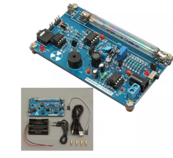
项目是在我买了一个现成的 Geiger 计数器套件之后开始的。
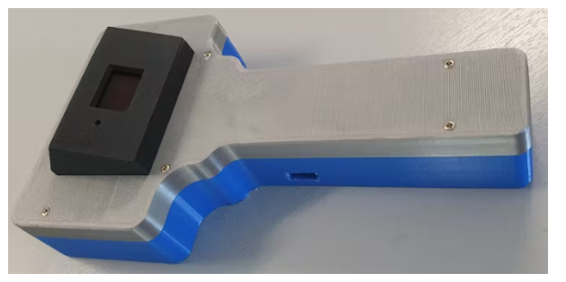
我的整个想法是把这个套件放在一个 3D 打印的外壳中,这样完整的盖革计数器套件就可以手持了。最终结果如下图所示:
第 1 步:系统设计
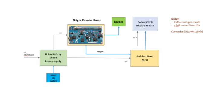
手持式盖革计数器的设计如下图所示:
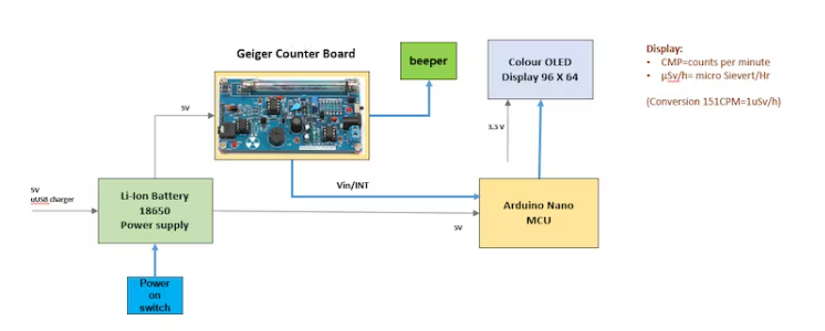
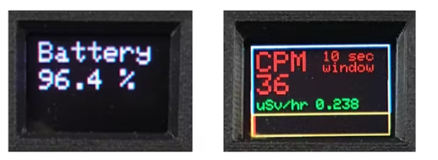
盖革计数器配备 0.96 英寸彩色 OLED 显示屏,可通过一个简单的因子告知用户测量的 CPM(测量每分钟电离事件的检测率)以及剂量当量(以 µSv/hr 为单位) 151 可以在文献中找到所使用的盖革-米勒 (GM) 管的类型。
事实上,显示的 CPM 是计算一分钟计数的结果,通过测量每秒计数 (CPS) 并将这些测量值存储在涵盖过去十秒周期的数组中。过去 10 秒期间的总计数乘以 6 即可获得 CPM 值。
过去一秒的计数用于通过 OLED 显示屏上的条形图显示瞬时测量次数。这在高计数率的情况下很有用,或者当手持式计数器在辐射源上移动时发生计数率的快速变化时。
盖革计数器由 18650 型锂离子电池供电,可通过微型 USB 插头充电。Arduino Nano USB 端口也可用于软件更改。一个额外的蜂鸣器连接到 Geiger 计数器板上,以增强 GM 管中的电离声音。
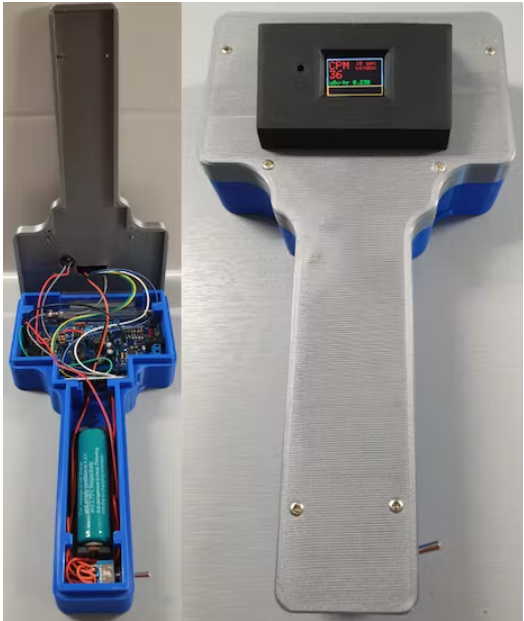
盖革计数器的所有电子设备都内置在 3D 打印外壳中:
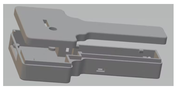
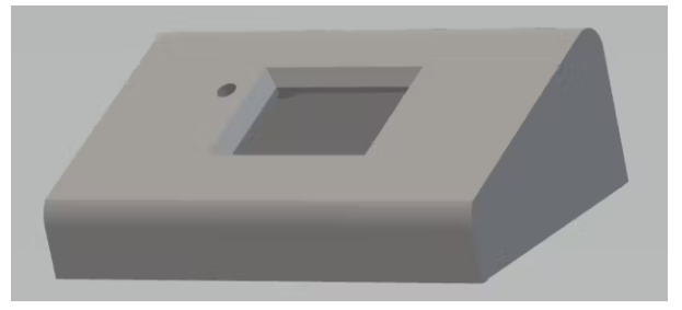
OLED 显示屏放在盖革计数器顶部的单独盒子中:
完全组装的版本:
第 2 步:制作盖革计数器组件
使用以下材料:
Arduino NANO 1
盖革计数器套件 1
0.96“ OLED 彩色显示屏 96 * 64 1
Micro USB 充电器板 18650 电池 1
3.7v 4000mAh 受保护的可充电 18650 锂离子电池 1
晶体管 BC547 1
蜂鸣器-12MM 1
电阻 1k Ohm 1
电子设计
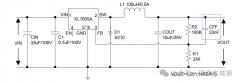
盖革计数器套件的电子设计如下电路图所示:
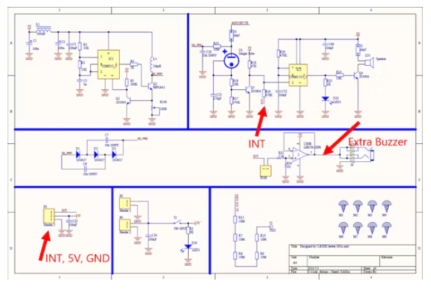
完整的盖革计数器设置的电路图如下:
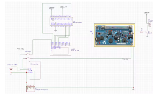
5V 电源由放置在 Micro USB 充电器板上的可充电锂离子电池提供。用于 OLED 显示器的 3、3 V 取自该板。
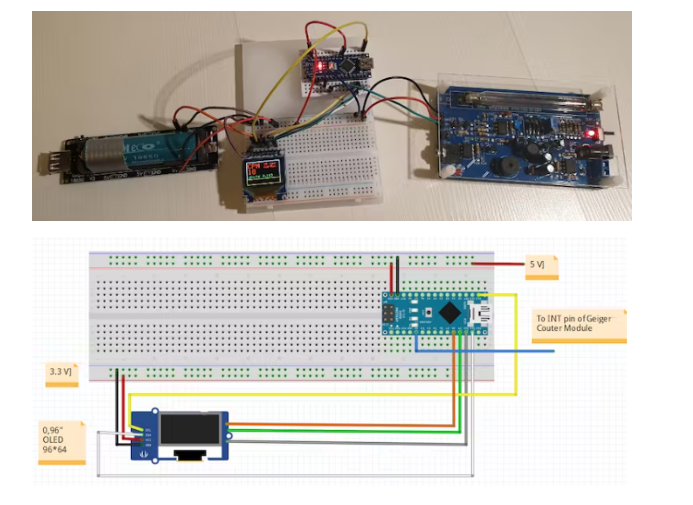
用于使用 ARDUINO IDE 测试和构建软件的面包板设置如下图所示:
组装
所有机械和电子零件的组装如下图所示:
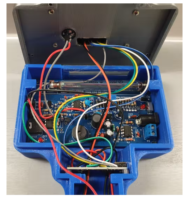
请注意,手持式盖革计数器没有任何电缆连接。
为了给 3、7V 锂离子电池充电,外壳上有一个单独的开口,用于(临时)连接微型 USB 插头。
额外的迷你 USB 连接可用于 Arduino Nano 的软件更新。
第 3 步:软件设计
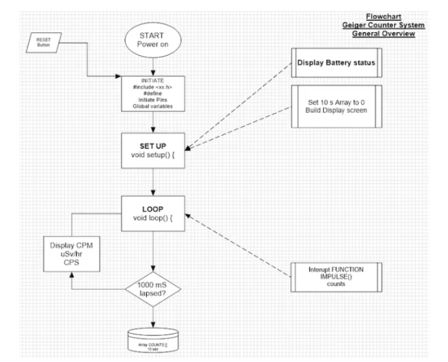
以下流程图显示了盖革计数器的一般软件设计:
0, 96” OLED 显示屏的视图如下:
完整的 Arduino 代码如下所示:
#include
#include
#include
//Connections for the OLED display
#define sclk 13 //SCL (blue wire)
#define mosi 11 //SDA (white wire)
#define cs 10 //CS (grey wire)
#define rst 9 //RES (green wire)
#define dc 8 //DC (yellow wire)
#define LOGtime 1000 //Logging time in milliseconds (1 second)
#define Minute 60000 //the period of 1 minute for calculating the CPM values
#define show endWrite
#define clear() fillScreen(0)
// Color definitions
#define BLACK 0x0000
#define BLUE 0x001F
#define RED 0xF800
#define GREEN 0x07E0
#define CYAN 0x07FF
#define MAGENTA 0xF81F
#define YELLOW 0xFFE0
#define WHITE 0xFFFF
Adafruit_SSD1331 display = Adafruit_SSD1331(cs, dc, rst);
int Counts = 0; //variable containing the number of GM Tube events withinthe LOGtime
unsigned long previousMillis= 0; //variablefor storing the previous time
int AVGCPM = 0; //variable containing the floating average number ofcounts over a fixed moving windo period
int TenSecCPM = 0;
int units = 0;
int tens = 0;
int hundreds = 0;
int thousands = 0;
float Sievert = 0;
int COUNTS[10]; // array for storing the measured amounts of impulses in10 consecutive 1 second periods
int t = 0;
////////////////////the setup code that follows,will run once after "Power On" or after a RESET///////////////////
void setup() {
Serial.begin(115200);
display.begin();
display.fillScreen(BLACK);
floatBattery = analogRead(A3); //(orange wire)
floatBattPerc = 100 * (Battery/770);
//Serial.print("battery value = "); Serial.println (Battery); Serial.print("battery percentage = "); Serial.println (BattPerc);
display.setCursor(4,4);
display.setTextSize(2);
display.setTextColor(MAGENTA);
display.println("Battery");
display.setCursor(4,24);
display.print (int (BattPerc)); display.print("."); display.print (int((10*BattPerc)-(10*int(BattPerc))));display.print(" %");
delay(3000);
display.fillScreen(BLACK);
for(int x = 0; x < 10 ; x++) { //put all data in the Array COUNTS to 0 (Array positionsrun from 0 to 10;
COUNTS[x] = 0; //10 positions covering a period of 10 seconds
}
attachInterrupt(0, IMPULSE, FALLING); //define external interrupton pin D2/INT0 to start the interupt routine IMPULSE (green wire)
display.drawRect(0,0,96,64,WHITE);
display.setCursor(4,4);
display.setTextColor(RED);
display.setTextSize(2);
display.print("CPM");
display.setCursor(50,4);
display.setTextSize(1);
display.print("10 sec");
display.setCursor(50,12);
display.print("window");
display.setCursor(4,38);
display.setTextSize(1);
display.setTextColor(GREEN);
display.print("uSv/hr");
display.drawRect(0,48, 96, 16, YELLOW);
}
////////////////////////the loop code that follows,will run repeatedly until "Power Off" or a RESET/////////
void loop()
{
unsignedlong currentMillis= millis();
if(currentMillis - previousMillis >LOGtime)
{
previousMillis = currentMillis;
COUNTS[t] = Counts;
for (int y = 0; y < 10 ; y++) { //add all data in the Array COUNTS together
TenSecCPM = TenSecCPM + COUNTS[y]; //and calculate the rolling average CPM over a 10 secondperiod
}
AVGCPM = 6* TenSecCPM;
TenSecCPM = 0;
t++ ;
if (t > 9) { t = 0 ;}
//Serial.print ("COUNTS "); Serial.print(t);Serial.print (" = ");Serial.println (COUNTS[t]);
display.fillRect(4,20,90,17,BLACK); // clear the CPM value field on the display
display.setCursor(4,20);
display.setTextColor(RED);
display.setTextSize(2);
display.println(AVGCPM);
//Serial.print ("AVGCPM = "); Serial.print(AVGCPM); //Serial.print (" CPM = "); Serial.println(CPM);
display.fillRect(45,38,50,10,BLACK); //clear the uSv/Hr value field on the display
display.setCursor(45,38);
display.setTextColor(GREEN);
display.setTextSize(1);
Sievert = (AVGCPM /151.0) ; //Serial.print (" Sievert = ");Serial.println (Sievert);
units = int (Sievert); //Serial.print ("units = "); Serial.println(units);
tens = int ((10*Sievert) - (10*units)); //Serial.print ("tens = "); Serial.println(tens);
hundreds = int ((100*Sievert) - (100*units) - (10* tens)); //Serial.print ("hundreds = "); Serial.println(hundreds);
thousands = int ((1000*Sievert) - (1000*units) - (100*tens) - (10*hundreds)); //Serial.print ("thousands ="); Serial.println (thousands);
display.print (units); display.print("."); display.print (tens); display.print (hundreds);display.println (thousands);
display.fillRect(1,49,94,14,BLACK); // clear the CPM indicator field on the display
display.fillRect(1,49,Counts,14,RED); //fill the CPM indicator field on the display
Counts = 0;
}
}
//////////////////END ofLOOP////////////////////////////////////
/////////////////////////////////Hereafter follows the Function for counting the number of impulses from Geiger Counter kit
void IMPULSE()
{
Counts++;
}
代码中最重要的部分是中断函数,当测量到 Geiger Counter 的 GM 管上的脉冲会触发 Geigercounter 的 INT 输出(通过使其在短时间内变为低电平)时调用。INT信号连接到引脚D2(Arduino Nano的外部中断引脚INT0):
attachInterrupt(0, IMPULSE, FALLING);
INT 信号将启动中断程序 IMPULSE () 以将 Counts 增加 1:
void IMPULSE() {Counts++ ; }
经过 1000 ms后:
整数 Counts 被放回 0
数组 COUNTS [ ] 填充了过去 1000 毫秒内测量的计数数
过去 10 秒的总计数是通过将数组 COUNTS [ ] 中的所有数字相加并乘以 6 以在显示屏上显示 CPM 值来计算的。
以 µSv/hr 表示的剂量当量是通过 CPM 值除以 151 计算得出的(该值可在文献中找到)。
在彩色 OLED 显示屏上,根据过去一秒的计数值显示一个红色条,因此实际上呈现的是 CPS 值(每秒计数)
上一篇:示波器电压探头和电流探头一样吗


 关注微信
关注微信