The circuit of Figure 1 produces an
accura
te variable-frequency sine wave f
or use as a general-purpose reference signal. It includes an 8th-order ellipt
ic, switched-capacitor lowpass filter (IC3) that is clocked with a 100kHz square wave generated by microcontroller IC2. (Any other convenient squarewave source is also acceptable.) The microcontroller is clocked by a 10MHz oscillator module. A voltage supervisor (IC1) ensures correct opera
tion in the event of a power failure. IC3 sets the filter's cutoff frequency at 1/100 the clock frequency.
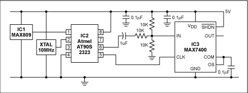
Figure 1. By removing harmonics from a square wave, this circuit generates an accurate and
adjustable sine-wave output.
The 8th-order elliptic filter's sharp rolloff sharply reduces the harmonic amplitudes in a 1kHz square-wave input, thereby producing a near-pe
rfect 1kHz sine wave at its output. Using divider-ch
ain
logic or a processor, you
can then create a digitally adjustable sine-wave source by adjusting the clock and input frequencies while maintaining a ratio of 100:1 between them. For the microcontroller shown, software to implement this idea is available for download. (.asm, 4K)
To prevent clip
ping at the positive and negative peaks, attenuate the input signal and superimpose it on a
dc level of VCC/2. The result (for a 5V input) is a 2.25V peak-to-peak output.
A
similar version of this article appeared in the May 15, 2003 issue of EDN magazine.


 关注微信
关注微信