时间:2023-01-01 10:08
人气:
作者:admin
为了让任何项目活跃起来,我们需要使用传感器。传感器充当所有嵌入式应用的眼睛和耳朵,它帮助数字微控制器了解这个真实模拟世界中实际发生的事情。在本教程中,我们将学习如何将超声波传感器HC-SR04与PIC微控制器连接。
HC-SR04是一种超声波传感器,可用于测量2厘米至450厘米(理论上)之间的距离。该传感器已通过安装到许多涉及障碍物检测、距离测量、环境映射等的项目中证明了自己的价值。在本文的最后,您将了解该传感器的工作原理,以及如何将其与PIC16F877A微控制器连接以测量距离并将其显示在LCD屏幕上。听起来很有趣吧!!所以让我们开始吧...
所需材料:
带编程设置的 PIC16F877A 单片机
液晶16*2显示屏
超声波传感器 (HC-SR04)
连接线
超声波传感器如何工作?
在我们进一步讨论之前,我们应该知道超声波传感器的工作原理,以便我们可以更好地理解本教程。本项目中使用的超声波传感器如下所示。
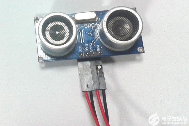
正如你所看到的,它有两个圆形的眼睛,像投影一样,四个针从中伸出来。两个眼睛状的投影是超声波(以下简称US波)发射器和接收器。发射器以 40Hz 的频率发射美国波,该波在空气中传播并在感应到物体时被反射回来。接收机观察到返回的波。现在我们知道这个波被反射并回来所需的时间,美国波的速度也是普遍的(3400cm/s)。使用这些信息和下面的高中公式,我们可以计算所覆盖的距离。
Distance = Speed × Time
现在我们知道了美国传感器的工作原理,让我们如何使用四个引脚将其与任何MCU / CPU接口。这四个引脚分别是Vcc,触发器,回声和接地。该模块工作在+5V电压下,因此Vcc和接地引脚用于为模块供电。另外两个引脚是我们用来与MCU通信的I / O引脚。触发引脚应声明为输出引脚,并设置为高电平 10uS,这将以 8 周期声波的形式将 US 波传输到空气中。一旦观察到波,回波引脚将在美国的波返回传感器模块所花费的确切时间间隔内变为高电平。因此,此Echo 引脚将被声明为输入,并且将使用计时器来测量引脚的高电平。这可以通过下面的时序图进一步理解。
电路图:
超声波传感器与PIC16F877A接口的完整电路图如下所示:
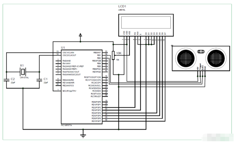
如图所示,该电路只涉及LCD显示屏和超声波传感器本身。美国传感器可由+5V供电,因此直接由7805稳压器供电。传感器有一个输出引脚(触发引脚)连接到引脚 34 (RB1),输入引脚(回波引脚)连接到引脚 35 (RB2)。完整的引脚连接如下表所示。

对 PIC 微控制器进行编程:
本教程的完整程序在本页末尾给出,下面我将代码解释为小意思的完整块供您理解。
在内部,主要功能我们像往常一样从初始化IO引脚和其他寄存器开始。我们定义LCD和美国传感器的IO引脚,并通过将其设置为在1:4预标量下工作并使用内部时钟(Fosc / 4)来启动定时器1寄存器
TRISD = 0x00; //PORTD declared as output for interfacing LCD
TRISB0 = 1; //Define the RB0 pin as input to use as interrupt pin
TRISB1 = 0; //Trigger pin of US sensor is sent as output pin
TRISB2 = 1; //Echo pin of US sensor is set as input pin
TRISB3 = 0; //RB3 is output pin for LED
T1CON=0x20; //4 pres-scalar and internal clock
定时器1是PIC16F877A中使用的16位定时器,T1CON寄存器控制定时器模块的参数,结果将存储在TMR1H和TMR1L中,因为它是16位结果,前8个将存储在TMR1H中,接下来的8个存储在TMR1L中。此定时器可以分别使用 TMR1ON=0 和 TMR1ON=1 打开或关闭。
现在,计时器可以使用了,但是我们必须将美波从传感器中发送出去,为此,我们必须将触发引脚保持高电平10uS,这是通过以下代码完成的。
Trigger = 1;
__delay_us(10);
Trigger = 0;
如上面的时序图所示,Echo引脚将保持低电平,直到波返回,然后在波返回所需的确切时间内变为高电平并保持高电平。这个时间必须由定时器1模块测量,可以通过以下行完成
while (Echo==0);
TMR1ON = 1;
while (Echo==1);
TMR1ON = 0;
测量时间后,结果值将保存在寄存器TMR1H和TMR1L中,这些寄存器必须进行杵状收集以获得16位值。这是通过使用下面的行完成的
time_taken = (TMR1L | (TMR1H<<8));
此time_taken将以字节形式显示,要获得实际时间值,我们必须使用以下公式。
Time = (16-bit register value) * (1/Internal Clock) * (Pre-scale)
Internal Clock = Fosc/4
Where in our case,
Fosc = 20000000Mhz and Pre-scale = 4
Hence the value of Internal Clock will be 5000000Mhz and the value of time will be
Time = (16-bit register value) * (1/5000000) * (4)
= (16-bit register value) * (4/5000000)
= (16-bit register value) * 0.0000008 seconds (OR)
Time = (16-bit register value) * 0.8 micro seconds
在我们的程序中,16位寄存器的值存储在变量time_taken中,因此下面的行用于以微秒为单位计算time_taken
time_taken = time_taken * 0.8;
接下来,我们必须找到如何计算距离。众所周知,距离=速度*时间。但是这里的结果应该除以 2,因为波同时覆盖了发射距离和接收距离。我们波(声音)的速度是34000厘米/秒。
Distance = (Speed*Time)/2
= (34000 * (16-bit register value) * 0.0000008) /2
Distance = (0.0272 * 16-bit register value)/2
所以距离可以用厘米计算,如下所示:
distance= (0.0272*time_taken)/2;
计算距离和时间的值后,我们只需在LCD屏幕上显示它们即可。
使用PIC和超声波传感器测量距离:
建立连接并上传代码后,实验设置应如下图所示。
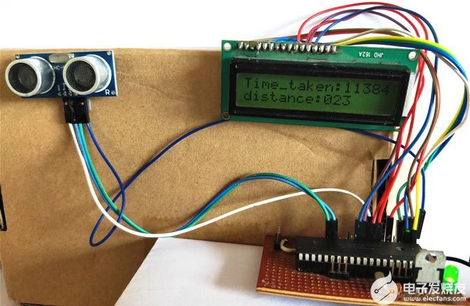
现在在传感器之前放置一个对象,它应该显示对象与传感器的距离。您还可以注意到波传输和返回所花费的时间以微秒为单位。
/*
Interfacing Ultrasonic sensor with PIC16F877A
* Code by: B.Aswinth Raj
* Dated: 19-07-2017
* More details at: www.CircuitDigest.com
*/
#define _XTAL_FREQ 20000000
#define RS RD2
#define EN RD3
#define D4 RD4
#define D5 RD5
#define D6 RD6
#define D7 RD7
#define Trigger RB1 //34 is Trigger
#define Echo RB2//35 is Echo
#include
#pragma config FOSC = HS // Oscillator Selection bits (HS oscillator)
#pragma config WDTE = OFF // Watchdog Timer Enable bit (WDT disabled)
#pragma config PWRTE = ON // Power-up Timer Enable bit (PWRT enabled)
#pragma config BOREN = ON // Brown-out Reset Enable bit (BOR enabled)
#pragma config LVP = OFF // Low-Voltage (Single-Supply) In-Circuit Serial Programming Enable bit (RB3 is digital I/O, HV on MCLR must be used for programming)
#pragma config CPD = OFF // Data EEPROM Memory Code Protection bit (Data EEPROM code protection off)
#pragma config WRT = OFF // Flash Program Memory Write Enable bits (Write protection off; all program memory may be written to by EECON control)
#pragma config CP = OFF // Flash Program Memory Code Protection bit (Code protection off)
//LCD Functions Developed by Circuit Digest.
void Lcd_SetBit(char data_bit) //Based on the Hex value Set the Bits of the Data Lines
{
if(data_bit& 1)
D4 = 1;
else
D4 = 0;
if(data_bit& 2)
D5 = 1;
else
D5 = 0;
if(data_bit& 4)
D6 = 1;
else
D6 = 0;
if(data_bit& 8)
D7 = 1;
else
D7 = 0;
}
void Lcd_Cmd(char a)
{
RS = 0;
Lcd_SetBit(a); //Incoming Hex value
EN = 1;
__delay_ms(4);
EN = 0;
}
void Lcd_Clear()
{
Lcd_Cmd(0); //Clear the LCD
Lcd_Cmd(1); //Move the curser to first position
}
void Lcd_Set_Cursor(char a, char b)
{
char temp,z,y;
if(a== 1)
{
temp = 0x80 + b - 1; //80H is used to move the curser
z = temp>>4; //Lower 8-bits
y = temp & 0x0F; //Upper 8-bits
Lcd_Cmd(z); //Set Row
Lcd_Cmd(y); //Set Column
}
else if(a== 2)
{
temp = 0xC0 + b - 1;
z = temp>>4; //Lower 8-bits
y = temp & 0x0F; //Upper 8-bits
Lcd_Cmd(z); //Set Row
Lcd_Cmd(y); //Set Column
}
}
void Lcd_Start()
{
Lcd_SetBit(0x00);
for(int i=1065244; i<=0; i--) NOP();
Lcd_Cmd(0x03);
__delay_ms(5);
Lcd_Cmd(0x03);
__delay_ms(11);
Lcd_Cmd(0x03);
Lcd_Cmd(0x02); //02H is used for Return home -> Clears the RAM and initializes the LCD
Lcd_Cmd(0x02); //02H is used for Return home -> Clears the RAM and initializes the LCD
Lcd_Cmd(0x08); //Select Row 1
Lcd_Cmd(0x00); //Clear Row 1 Display
Lcd_Cmd(0x0C); //Select Row 2
Lcd_Cmd(0x00); //Clear Row 2 Display
Lcd_Cmd(0x06);
}
void Lcd_Print_Char(char data) //Send 8-bits through 4-bit mode
{
char Lower_Nibble,Upper_Nibble;
Lower_Nibble = data&0x0F;
Upper_Nibble = data&0xF0;
RS = 1; // => RS = 1
Lcd_SetBit(Upper_Nibble>>4); //Send upper half by shifting by 4
EN = 1;
for(int i=2130483; i<=0; i--) NOP();
EN = 0;
Lcd_SetBit(Lower_Nibble); //Send Lower half
EN = 1;
for(int i=2130483; i<=0; i--) NOP();
EN = 0;
}
void Lcd_Print_String(char *a)
{
int i;
for(i=0;a[i]!='';i++)
Lcd_Print_Char(a[i]); //Split the string using pointers and call the Char function
}
/*****End of LCD Functions*****/
int time_taken;
int distance;
char t1,t2,t3,t4,t5;
char d1,d2,d3;
int main()
{
TRISD = 0x00; //PORTD declared as output for interfacing LCD
TRISB0 = 1; //DEfine the RB0 pin as input to use as interrupt pin
TRISB1 = 0; //Trigger pin of US sensor is sent as output pin
TRISB2 = 1; //Echo pin of US sensor is set as input pin
TRISB3 = 0; //RB3 is output pin for LED
T1CON=0x20;
Lcd_Start();
Lcd_Set_Cursor(1,1);
Lcd_Print_String("Ultrasonic sensor");
Lcd_Set_Cursor(2,1);
Lcd_Print_String("with PIC16F877A");
__delay_ms(2000);
Lcd_Clear();
while(1)
{
TMR1H =0; TMR1L =0; //clear the timer bits
Trigger = 1;
__delay_us(10);
Trigger = 0;
while (Echo==0);
TMR1ON = 1;
while (Echo==1);
TMR1ON = 0;
time_taken = (TMR1L | (TMR1H<<8));
distance= (0.0272*time_taken)/2;
time_taken = time_taken * 0.8;
t1 = (time_taken/1000)%10;
t2 = (time_taken/1000)%10;
t3 = (time_taken/100)%10;
t4 = (time_taken/10)%10;
t5 = (time_taken/1)%10;
d1 = (distance/100)%10;
d2 = (distance/10)%10;
d3 = (distance/1)%10;
Lcd_Set_Cursor(1,1);
Lcd_Print_String("Time_taken:");
Lcd_Print_Char(t1+'0');
Lcd_Print_Char(t2+'0');
Lcd_Print_Char(t3+'0');
Lcd_Print_Char(t4+'0');
Lcd_Print_Char(t5+'0');
Lcd_Set_Cursor(2,1);
Lcd_Print_String("distance:");
Lcd_Print_Char(d1+'0');
Lcd_Print_Char(d2+'0');
Lcd_Print_Char(d3+'0');
}
return 0;
}
上一篇:思岚科技自研激光雷达的初心与野望


 关注微信
关注微信