Abstract: The MAX4390 opera
tional amplifier configured in a 3-pole, low-pass Sallen-Key fil
ter that provides a Butterw
orth response with a bandwidth of -3dB at 5.25MHz. This circuit
can be used for video anti-aliasing and reconstruction filtering for composite (CVBS) or S-Video signals in standard definition digital TV (
SDTV) appl
ications. The circuit is designed to drive a 75Ω termination, common in video applications, with an overall g
ain of 1.
The Sallen-Key realization of a 5.25MHz, 3-Pole Butterworth filter shown in Figure 1 has a gain of 2V/V and is capable of driving 75Ω b
ack-terminated coax to an overall gain of 1. Used to reconstruct component-video (Y, Pb, Pr) and RGB signals, this filter has an insertion loss of >20db at 13.5MHz and >40db at 27MHz (Figure 2). Like the anti-aliasing filter before an
ADC, this filter is used to remove the higher-frequency replicas of a signal following a
DAC.
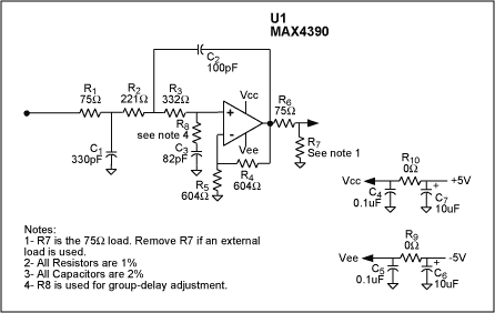
Figure 1. This 3-pole Butterworth video-reconstruction filter has
adjustable group delay.
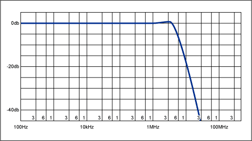
Figure 2. Typical filter response for circuit of Figure 1 with R3 + R8 = 332Ω.
To preserve quality in the video waveform, one should minimize group-delay variations in the filter and also any group-delay differential between filte
rs. That capability requires a means for adjusting the filter's group delay without affecting its bandwidth. In Figure 1, the addition of R8 in series with C3 and R3 creates a lag-lead network. Keeping the sum of R3 and R8 constant and equal to the original R3 value preserves bandwidth by preserving the dominant-pole frequency. Increasing the R3 value, on the other hand, introduces a "lead" term that lowers group delay by reducing the rate of change in phase.
For R8 = 0Ω and R3 = 332Ω in the circuit shown, the average group-delay variation over the filter bandwidth is about 25ns Raising R8 to 31.6Ω and lowering R3 to 301Ω drops the variation to about 15ns, and setting R8 = 59Ω with R3 = 274Ω drops it to about 7ns The last case affects band-edge selectivity slightly (<0.5dB), but does not change the filter's -3dB bandwidth. These group-delay variations are shown in Figure 3.
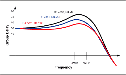
Figure 3. Selected values of R8 and R3 (see text) allow control of group-delay variation over the filter's passband.
A
similar version of this article appeared in the August 8, 2002 issue of EDN magazine.


 关注微信
关注微信