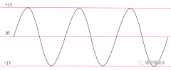
Abstract: The digital, pulse-width-modula
tion (PWM) output av
ailable from many microprocess
ors is based on an in
ternal 8- or 16-bit counter and features a prog
rammable duty cycle. It is suitable for
adjusting the output of an LCD driver, a negative-voltage
LED driver, or a current-controlled LED driver.
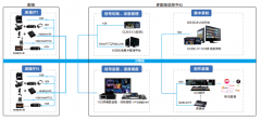
The digital, pulse-width-modulation (PWM) output available from many microprocessors is based on an internal 8- or 16-bit counter and features a programmable duty cycle. It is suitable for adjusting the output of an LCD driver (Figure 1), a negative-voltage LED driver (Figure 2), or a current-controlled LED driver (Figure 3).
Figure 1. LCD Driver with positive output voltage.
Figure 2. LCD driver with negative output voltage.
Figure 3. Current-controlled LED driver.
The circuit consists
simply of a PWM source, capacitor C, and resistors RD and RW. For CMOS outputs, you calculate the open-circuit output voltage as:

where D is the PWM duty cycle and VDD is the
logic supply voltage. The control circuit's output imp
edance is the sum of resistor values RW and RD:

For the circuit of Figure 1, the output voltage (VOUT) is a function of the PWM average voltage (VCONT):
where
VREF is the reference voltage at the feedb
ack input.
Bear in mind that the initial charge on filter capacitor C produces a turn-on transient. The capacitor forms a time constant with RCONT, which causes the output to initialize at a voltage higher than that intended. You
can minimize this overshoot by scaling the value of RD as high as possible with respect to R1 and R2. As an alternative, the µP can disable the LCD until the PWM voltage stabilizes.
For Figure 2, the output voltage (VOUT) is a function of the PWM average voltage (VCONT):
where VREF is the reference voltage at the feedback input.
For Figure 3, the output current (IOUT) is a function of the PWM average voltage (VCONT):
where VREF is the reference voltage at the SET output and K is the current-scaling factor.
RD isolates the capacitor from the feedback loop in these PWM-adjustment methods. Assuming a stable voltage at the feedback point, the following equation defines the lowpass filter's cutoff frequency:
where R = RW

RD. If RD >> RW, R ≈ RW. To minimize ripple voltage at the output, you should set the cutoff frequency at least two decades below the PWM frequency.


 关注微信
关注微信