Abstract: This appl
ication no
te provides det
ails on how to connect the MAX6958 and MAX6959
LED display drivers to LED displays f
or clock applications. Standard 1, 2, 3, and 4 digit displays, off-the-shelf clock displays are discussed. A suggested wiring scheme for a custom clock display is given.
This applica
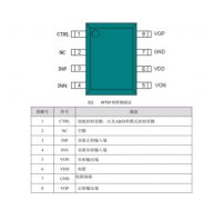
tion note discusses general considerations for using the MAX6958 or MAX6959 for applications displaying time. The MAX6958 and MAX6959 are 4-digit, 9-segment LED drivers which use a reduced
pin count multiplexing scheme to drive 36 segments using only 10 drive pins (Table 1). The pin connections from the MAX6958/59 to the LED digits is not the standard connection, as Table 1 shows. Pins 4 to 7 share duty as both common cathode and anode drivers, depending on the multiplex cycle.
Table 1. Standard Driver Connection for MAX6958/59
| |
DIG/SEG 0
Pin 4 |
DIG/SEG 1
Pin 5 |
DIG/SEG 2
Pin 6 |
DIG/SEG 3
Pin 7 |
SEG 4
Pin 11 |
SEG 5
Pin 12 |
SEG 6
Pin 13 |
SEG 7
Pin 14 |
SEG 8
Pin 15 |
SEG 9/IRQ
Pin 3 |
|
LED Digit 0 |
CCO |
SEG 0 |
SEG g |
SEG f |
SEG e |
SEG d |
SEG c |
SEG b |
SEG a |
SEG 4 (dp) |
|
LED Digit 1 |
SEG 1 |
CC1 |
SEG g |
SEG f |
SEG e |
SEG d |
SEG c |
SEG b |
SEG a |
SEG 5 (dp) |
|
LED Digit 2 |
SEG g |
SEG f |
CC2 |
SEG 2 |
SEG e |
SEG d |
SEG c |
SEG b |
SEG a |
SEG 6 (dp) |
|
LED Digit 3 |
SEG g |
SEG f |
SEG 3 |
CC3 |
SEG e |
SEG d |
SEG c |
SEG b |
SEG a |
SEG 7 (dp) |
The MAX6958/59
can be used with all normal common cathode single-digit and dual-digit display types, but cannot be used with normal triple-digit or quad-digit displays (Figure 1). Unfortunately, standard clock 'stick' displays (which integrate colon and annunciator segments as well as the 4 time digits) can't be used either. The reason these displays can't be used is that the internal die-to-die wiring precludes the shared cathode/anode interconnection that the MAX6958/59 needs. Examples of standard clock displays are shown in Figures 2 to 4.
Figure 1. Off-the-shelf standard LED digits - single, dual, triple, and quad.
Figure 2. 4-digit clock display.
Figure 3. 4-digit clock display for either 24-hour time and 12-hour time.
Figure 4. 4-digit clock display for 12-hour time only.
The MAX6958/59 can drive a display of segment complexity such as Figure 5. This display uses 4 full digits, but without the decimal pl
ace (dp) segments. Three annunciator segments provide the common al
arm, AM, PM functions on the left. The colon segment is made from two LED dice connected in parallel and driven together as one LED, per standard clock module practice. Four more annunciato
rs are shown on the right, and these could be dp segments for the 4 digits as desired. Individual applications will vary from this of course, but this example shows the full LED drive capability of the MAX6958/59. If the MAX6959's key-scan IRQ output is required, then the four annunciators SEG 4 to SEG 7 won't be available, as the segment drive and IRQ function share a common pin.
Figure 5. Drive capability of the MAX6958/59 with a 4-digit clock display.
There are two choices for implementing the display design shown in Figure 8, knowing that a standard display is not available. First, the display can be built from off the shelf LEDs, such as single or dual digit displays, and discrete LEDs. An example of this approach using dual-digit displays is shown in Figure 6.
Figure 6. Building a 4-digit clock display with dual-digits and discrete LEDs.
For high volume applications, ordering makes sense because at volume the cost of a custom display will be the same as a standard display anyway. The "ideal" internal wiring a custom display is shown in Figure 7. As drawn, the display allows the hex
adecimal fonts to work correctly for Digit 0 to Digit 3. To implement this layout on a custom LED module, a 2-layer
PCB will be necessary. LED manufacturers can normally save cost by designing modules on a single layer boards instead of 2-layer. If lowest display cost is a priority, the best advice is to
simply ensure that the Table 1 interconnect is followed, and let the LED manufacturer wire the LEDs in whatever pattern is necessary to make a single layer board. It then becomes a software issue to re-map the segment order.
Figure 7. Wiring diag
ram for a custom 4-digit clock display.

 关注微信
关注微信