时间:2009-04-27 10:00
人气:
作者:admin
Figure 1. This circuit provides a logarithmic-dimming capability for white LEDs.
To control the LED brightness, op amp U2 monitors the difference between the high-side voltage and the wiper voltage of digital potentiometer U1. The op amp then multiplies that voltage by a gain to set the maximum output current. Zero resistance at the pot's W1 terminal corresponds to minimum LED current, and therefore minimum brightness. Because the SET voltage is fixed (at 0.6V), any voltage change at the left side of R5 changes ISET, and the resulting change in LED currents changes their brightness level. R5 sets the maximum LED current:
R5 = 215x0.6/ILED(Desired)
where ILED is the current through one LED.
U1 is a digital potentiometer with logarithmic taper and an analog-voltage wiper for which each tap corresponds to 1dB of attenuation between H1 and W1 (pins 11 and 9). It contains two pots controlled by a 16-bit code via a 3-wire serial interface. To set the LED current, drive RST-bar high and clock 16 bits into the D terminal of U1, starting with the LSB. Each pulse at CLK enters a bit into the register.
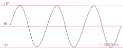
The circuit uses only one pot, so bits 0 through 7 are "don't care" bits. Bits 8 through 14 determine the wiper position: bits 8 through 13 set the code, and bit 14 is "mute." (Logic one at bit 14 produces the lowest-possible output current by setting the left side of R5 at approximately 0.599V.) After entering all 16 bits, enter the code and change the brightness level by driving RST-bar high. Figure 2 shows the logarithmic relationship between an LED current and the pot's input code.
Figure 2. LED current vs. input code for the Figure 1 circuit.
This design idea appeared in the June 10, 2004 issue of EDN magazine.
上一篇:高亮度LED恒流驱动电路设计
下一篇:白色LED的恒流驱动


 关注微信
关注微信