Abstr
act: Besides reducing the number of required GPIO lines from eleven to two, this circuit also provides prog
rammable contrast and backlight control.
Most LCD character displays connect to the outside w
orld through a controller
IC, such as the HD44780 (Hitachi) or equivalent. That interface has serious drawbacks, however. It uses up a large number of the microcontroller's general-purpose input/output (GPIO)
pins, and it isn't capable of providing digital-contrast or backlight-intensity control.
The circuit in Figure 1 reduces the required number of GPIOs from eleven to two, and also provides digital control of the LCD's contrast and backlight in
tensity. A versa
tile I/O-port expander (U1) emulates the typical 8-bit I/O port of a microcontroller. You
can implement this interface with little or no extra code if your microcontroller integrates an I²C‡ peripheral. As an alternative, you can bit-bang the required signals through the regular GPIO pins.
Figure 1. Besides reducing the number of required GPIO lines from eleven to two, this circuit also provides programmable contrast and backlight control.
Op amp U3B buffe
rs DAC output OUT1, which controls the contrast voltage. DAC output OUT0 controls a constant-current sink consisting of op amp U3A,
MOSFET N1, and resistors R1, R5, and R6. This current sink draws 500mA when the DAC voltage output is at full scale.
You might need to
adjust the
maximum
LED backlight current according to the size of the LCD display. To do that, use the following equations to calculate resistor values R1, R5, and R6:
where
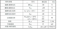
VDD(min) = minimum anode supply voltage (4.5V typ),
VFLED(max) = maximum forward LED voltage,
IFLED(max) = maximum forward LED current,
RDS(ON) = on-resistance of switch N1,
VFS(DAC) = full-scale voltage output of DAC,
PR1 = minimum power rating of resistor R1, and R6 = 10kΩ.
This application note appeared as a design idea in the June 9, 2005 issue of Electronic Design magazine.
‡Purchase of I²C components from Maxim Integrated Products, Inc., or one of its
sublicensed Associate Companies, conveys a license under the Philips I²C Patent Rights to use these components in an I²C system, provided that the system conforms to the I²C Standard Specification defined by Philips.

 关注微信
关注微信